| |
CARDS
|
| |
 |
|
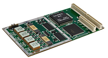
TA1-PMC2
PMC Interface Card
with Two Dual Redundant MIL-STD-1553B

- Provides considerably extended set of functions in comparison with cards of previous generation - TX/TE.
- I/O space is 32 16-bit words per terminal. Uses 1 interrupt line.
- 1 or 2 dual redundant terminals in the modes of bus controller (BC), remote terminal (RT), addressed message monitor (MTM) and addressed word monitor (MTW).
- Dual-port RAM 64K x 16 per terminal.
- Internal interrupt FIFO buffer 256 words deep.
- 32-bit programmable timer for message receiving.
- Programmable status timeout up to 64 us.
- In the BC mode allows organizing the automatic transfer of a message chain. Provides the programming of the response to error message with the possibility of automatic retry and switching the bus number. Status words masking has been implemented.
- In the RT mode there is a possibility to buffer the received messages for each subaddress. Programming the message receiving timer can be done upon the BC commands. There is a possibility to block messages receiving/transmitting for specified subaddresses.
- There are three basic modes of monitor operation: Message monitor, Word monitor and Combined monitor. All three modes allow specifying the RT address to use the device as the addressed monitor.
- In the addressed messages monitor mode, the module responds as an RT to the commands addressed to it and monitors messages from the addresses specified in the list.
- In the combined monitor mode the information is registered by the message monitor while being parsed as a message. In parallel the word monitor registers all words.
- In the word monitor mode the module responds to the commands addressed to it as an RT and receives all words transmitted via two buses.
- Possibility to test the transmitter/receiver and bus status.
- Single power supply source +5V.
|
| Document |
Size |
Last updated |
| TA1-PCI datasheet |
 |
49Kb |
15.06.2006 |
| TA program model description |
 |
52Kb |
15.06.2006 |
| Drivers (DOS, QNX, Windows, Linux) |
Details... |
|


